Clutch control
A logic-level MOSFET grounds L-O to energize the
A15 clutch relay — exactly what the OEM unit did, with no
mechanical contacts to burn.
Div.02 // Toyota MR2 SW20 · 88650-17120 / -17130
A purpose-built replacement for the failed 88650-17120 A/C amplifier, made for engine-swapped SW20s. It reads your factory sensors, drives your factory relays, and keeps the factory pressure protection in hardware — so the compressor, the freeze cycling, and both radiator fan stages all work the way Toyota intended.
From $25 · Built & tested from $199 · Ships within the US
Shipping today for engine-swapped cars and stock MY1991–92 cars (Unit A). Stock 1993–95 cars (Unit B) are open for pre-order, delivered within 30 days. See the lineup →
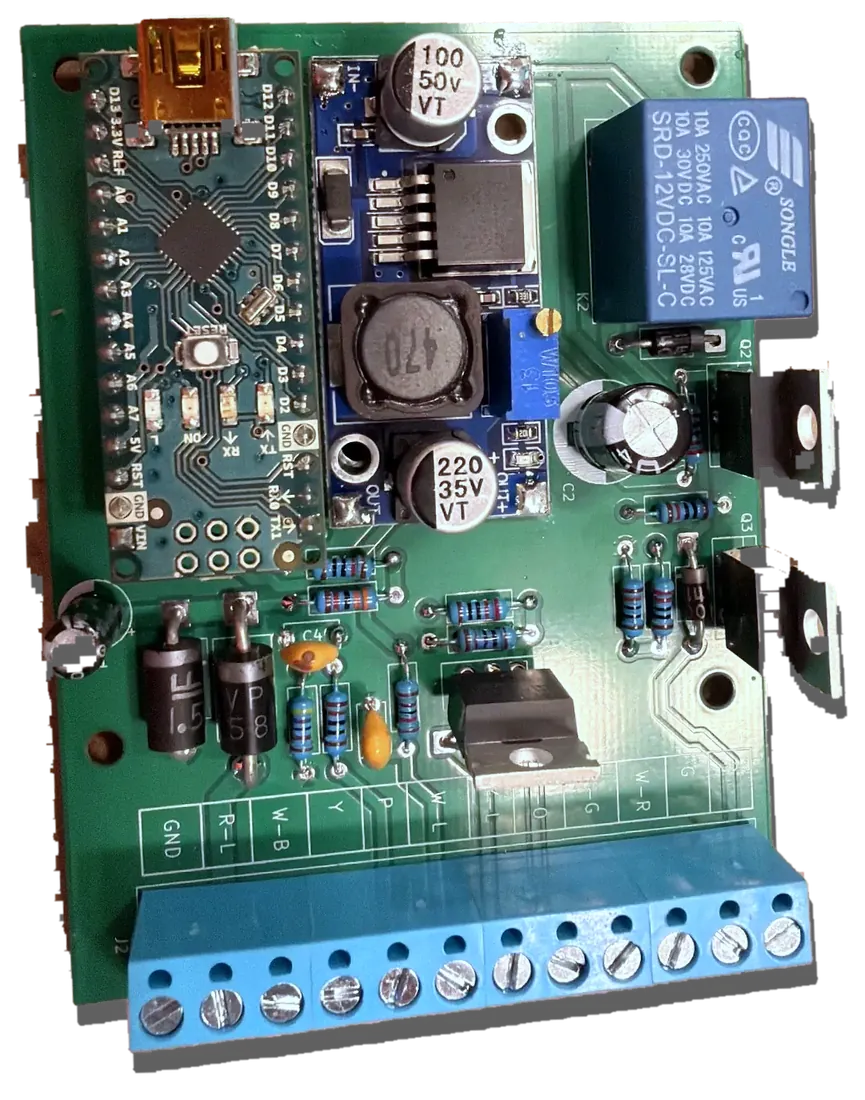
88650-17120
The beige amplifier under your dash. Discontinued.
$200
What an untested used one costs, when one surfaces at all — with no guarantee it isn't dead too. Tested, rebuilt units sell for $600+.
1 part
All it does is ground one wire. Everything else in your A/C system is probably fine.
Start here
Toyota fitted three different A/C amplifiers across the SW20 run. They look alike, they are not interchangeable, and between them the terminal numbering changed completely. Five minutes with a torch settles it — and it is the one thing you must get right before you order anything on this page.
It is the box the A9 harness plug goes into,
behind the centre console under the dash. On the label is a
Toyota part number beginning 88650-. That number
is the answer — not the year, not the engine.
Count the populated cavities in the A9 plug.
14 populated is the -17120 family. 16 is the -17130 family. The two
extra wires on the later car are a brown BR — the
amplifier's own output to the engine ECU — and a brown/white
BR-W strap.
US 1991 is almost always -17120. US 1993–95 is
-17130.
A US 1992 car has to be read off the label —
the changeover happened in December 1991, which falls inside
that model year. Any car built from December 1991 onward, in
any market, is -17130.
Then you want the Swap Edition — but only if
the car started life with a -17120. A swapped car
that came with a -17130 should wait for Unit B,
whose firmware can switch the extra outputs off.
| On the label | Your car | You need | Status |
|---|---|---|---|
88650-17120 | Engine swapped (2GR-FE, 1MZ, K-series…) | Swap Edition | In stock |
88650-17120 | Stock engine. MY1991–92 USDM/Canada, 5S-FE or 3S-GTE, either transmission. Europe LHD Dec 1989 – Dec 1991. | Unit A | In stock |
88650-17130 | Stock engine. MY1993–95 USDM and late-built 1992s. Japan Rev 2–5 and Europe, Dec 1991 onward. | Unit B | Pre-order · 30 days |
88650-17100 | Right-hand drive Rev 1 — Japan Oct 1989 – Dec 1991 (frames to SW20-0059265), UK/Europe RHD Dec 1989 – Dec 1991. | Unit C | Not available |
-17130 and falls under Unit B. Built earlier
it is the -17100 and there is no product for it yet.
Note that every Japanese SW20 also carries a second amplifier,
88650-20590, which no US or European car has — its
function is still unidentified, so a JDM fitment is not something I
will call proven.
The Swap Edition is built for one specific situation. Check these four things before you spend anything; if any of them is not you, the lineup has the unit that is.
88650-17120 — the beige unit
on early cars. That part number is what the Swap Edition was
designed against. A -17130 car needs
Unit B. B-W signal path, and it's how this controller hands
your ECU the idle-up request. If your ECU expects a ground
instead, talk to me before ordering. This takes ten minutes and tells you whether you need this part or something cheaper.
A low system won't engage the clutch no matter what controls it — the factory pressure switch cuts it off. Check the charge first.
L-O wire engages the clutch.
At the amplifier plug, jump the blue/orange wire to ground with the engine running. If the compressor kicks in and you get cold air, your compressor, clutch, relay, and refrigerant are all fine — the amplifier is the failure.
12 V shows up on the pink wire when you press it, but the clutch never engages. That's the amplifier failing to close the loop.
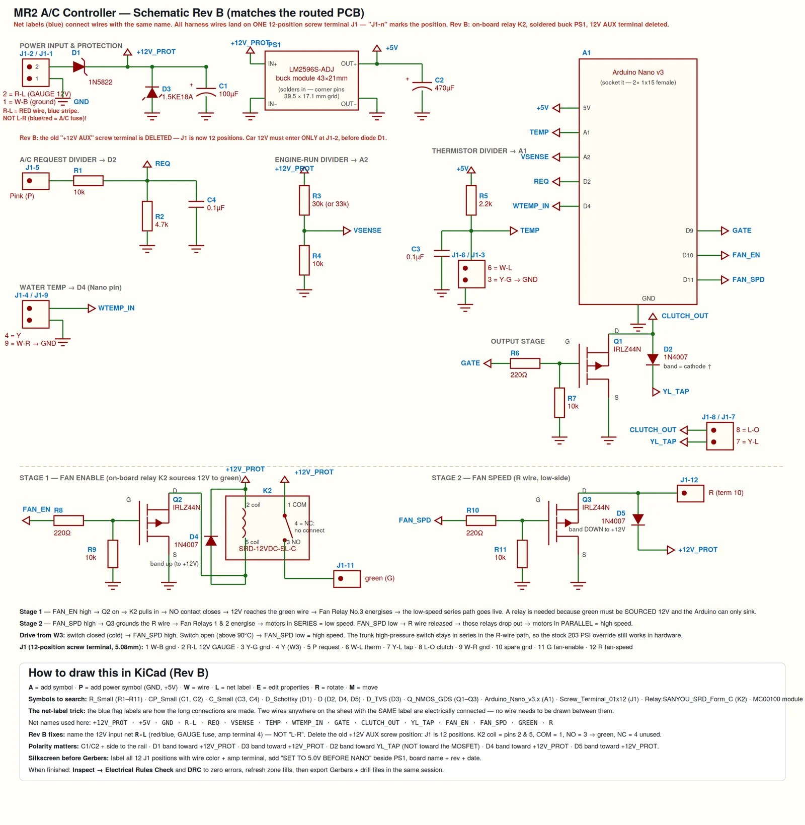
The factory amplifier had five jobs. This reproduces all five, from the same wires, at the same plug.
A logic-level MOSFET grounds L-O to energize the
A15 clutch relay — exactly what the OEM unit did, with no
mechanical contacts to burn.
Reads your factory evaporator thermistor and cycles the compressor with proper hysteresis plus minimum on/off timing. No short-cycling, no iced core.
Senses alternator charging voltage with hysteresis and a dip-grace timer, so the compressor's own engagement sag doesn't drop it out. Key-on with the engine off does nothing, same as stock.
An on-board relay sources 12 V to the fan enable circuit, and a second output holds the motors in series for LOW — releasing to parallel HIGH above ~90 °C. The factory behavior most replacements skip entirely.
Your A13 dual pressure switch still gates the relay's power feed. High or low refrigerant pressure cuts the compressor whatever the software thinks. That circuit is untouched.
The B-W wire — 12 V only while the clutch relay is
closed — is the factory signal path to the ECU's A/C input.
Tap it and your ECU raises idle under compressor load.
When you swap an engine into an SW20, the A/C amplifier loses half its job. The vacuum idle-up actuator it used to drive is gone with the old engine, and the igniter signal it watched for the high-RPM cutout belongs to an ignition system that isn't in the car anymore.
A swap ECU handles those itself. It just needs to be told the compressor is engaging — and it wants that as +12 V on the same wire that closes the clutch relay. So the controller's job gets simpler and cleaner, and everything left is A/C circuitry that's still pure MR2.
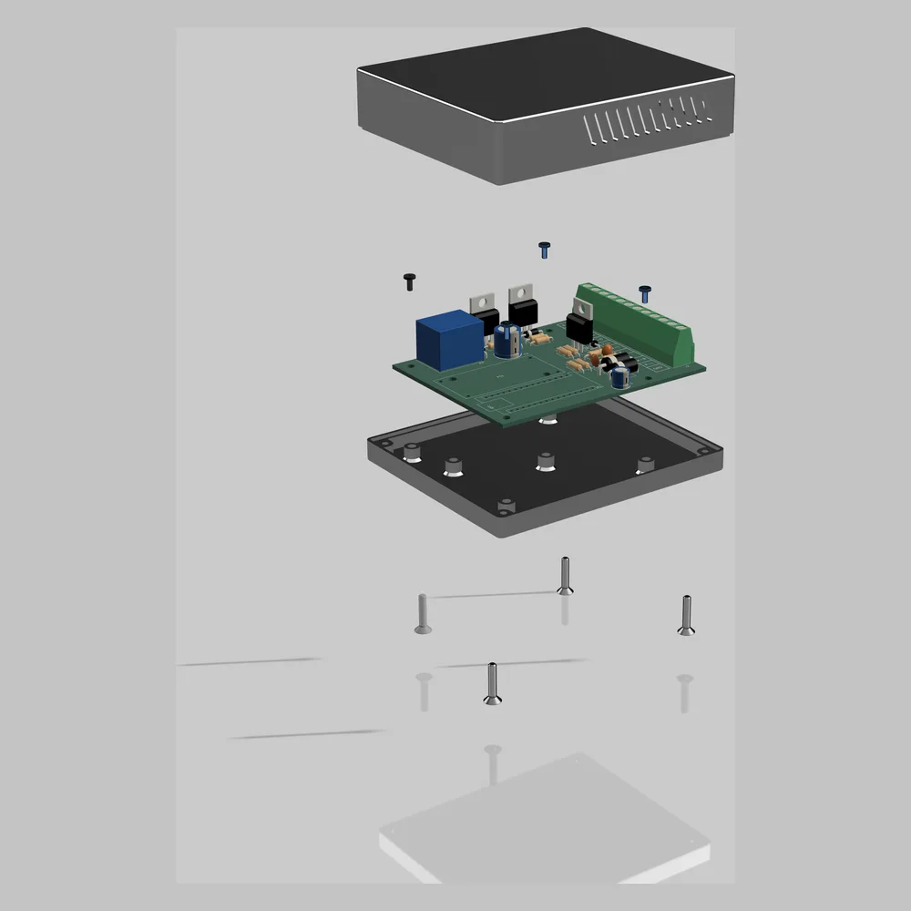
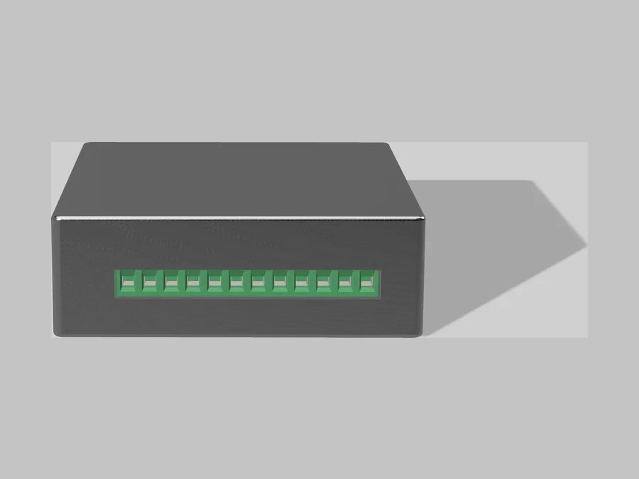
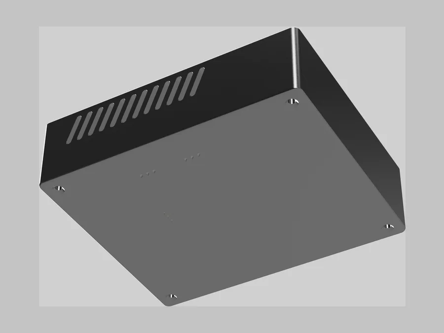
Board, enclosure, and hardware. The whole assembly is 90 × 70 mm. The housing is printed in ASA — not PLA — so it holds its shape through a closed-up summer behind the dash and won't go brittle in UV.
The lineup
Products here are named after the Toyota amplifier they replace. Units A and B share one PCB, one enclosure and one firmware base — what differs is which terminals get populated and which profile is loaded. Below is exactly where each one stands — and every unit comes the same three ways, at the same three prices: bare PCB, complete kit, or built and tested. What each option includes →
Replaces 88650-17120 on an engine-swapped SW20
For a car whose original engine and ECU are gone. Drives the compressor clutch with evaporator freeze protection and engine-running gating, plus both radiator-fan stages from the W3 switch and the A/C request.
It deliberately does not provide the turbo car's VSV idle-up ground, the igniter tach input or the 5S-FE automatic's ECU cut request. A swap car has none of those left to connect.
In stock — ships within the US
Replaces 88650-17120 on a stock car
MY1991–92 USDM and Canada, both engines, both transmissions; Europe LHD to December 1991. Everything the Swap Edition does, plus the three functions a stock car still needs: the VSV idle-up ground for the 3S-GTE, an opto-isolated igniter tach input with low-RPM clutch release, and the P-G input from a 5S-FE automatic ECU.
15-position terminal. A 5S-FE manual car simply leaves the turbo positions empty.
In stock — ships within the US
Replaces 88650-17130 on a stock car
MY1993–95 USDM and late-built 1992s; Japan Rev 2–5 and Europe from December 1991. Unit A plus the three things Toyota changed in 1993: the AC1 output that tells the ECU the compressor is on, W3 read as a temperature sensor rather than a switch, and the SELECT strap set by engine and transmission.
Same outline, same holes, same case as Unit A. One PCB, one enclosure, a firmware profile per unit.
Pre-order — delivered within 30 days
Would replace 88650-17100 — right-hand drive Rev 1
The first two years of right-hand-drive production: Japan from
October 1989 to December 1991 (frames to SW20-0059265), and
UK/Europe RHD cars from December 1989. From December 1991 these
cars carry the same -17130 as the US 1993 car and
fall under Unit B.
-17100 terminal map is simply unknown. There is no
schematic and no design. This is research, not a product.
Every terminal on the board was audited against the 1991 electrical wiring diagrams — page by page, wire by wire.
The routed 2-layer PCB was checked net-by-net against the netlist before a single board was ordered.
Boots with the clutch off. Loss of signal drops the compressor rather than latching it on. Reverse-polarity Schottky and a TVS sit at the supply input.
Identify the thermistor pair by measuring ~1.1 kΩ, never by pin number. The 12 V feed is R-L off the GAUGE fuse — not L-R, a different wire in the same loom. The W3 switch is a fan switch, not an overheat cutout, and is deliberately unused. These are the mistakes that cost me time; they're written down so they don't cost you any.
The wiring guide is plain English, in order, with a full J1 position map. No schematic literacy required.
Whichever unit your car needs, it comes three ways at the same three prices. Same board, same documentation pack, same firmware profile for your unit. The difference is how much of the work you want to do.
The board for your unit, on its own
$ 25
Ships in 3–5 business days
The fabricated board on its own. You buy the components and do the soldering.
Board + every component
$ 99
Delivered in about 2 weeks
Everything in one bag, parts already sourced to the exact specs that matter. You solder it.
Most popular
Assembled, flashed, bench-verified
$ 199
Built to order — allow 2–3 weeks
Assembled by hand, flashed for your car, and bench-tested before it ships. Wire it in and go.
Shipping is flat $8 in the US. International — email me and I'll quote it. Not sure which option? Take Built & Tested — it arrives flashed, bench-tested and in its case, so the only thing left to get right is your wiring. Then pick your unit below.
Same documentation at every tier, bare PCB included: the complete schematic, the plain-English wiring guide with all 43 wires numbered and a full J1 position map, the component list with the three substitutions that will bite you, the firmware source with the profile for your unit, the enclosure print files, the diagnostic checklist, and the design and board validation reports.
It arrives by email after your order. The files aren't published anywhere else and aren't sold on their own — they come with the hardware.
The factory electrical wiring diagrams aren't included — those are Toyota's, not mine to hand out. You'll want a copy; they're findable.
1991 · SW20 · 2GR-FE
This started because my own 1991 SW20 blew warm air and the part I needed hadn't been made in twenty years. Everything here was developed on that car, wired into that harness, and driven through a full summer. The product came second.
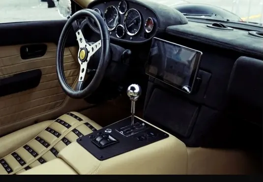
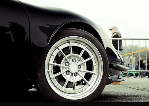
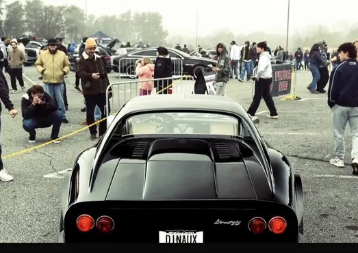
A hand-built Dino tribute on a 1991 MR2 chassis — UK body, 2GR-FE V6 with a 1GR compressor, manual gearbox. The A/C circuit underneath it is pure SW20, which is exactly why the controller works on any swapped car.
You splice at the A9 amplifier plug — the same plug the dead amplifier came out of. Nothing else in the car is modified, and the job is reversible if you ever find an OEM unit.
The safety that matters most never touches the microcontroller. Your A13 dual pressure switch still gates the clutch relay's power feed in hardware — if refrigerant pressure goes high or low, the compressor stops regardless of what any code is doing. On top of that, the board boots with the clutch off and drops the compressor on loss of signal rather than latching it on.
Yes, and this is where most amplifier workarounds fall short. The factory amplifier had three separate fan jobs and this reproduces all of them, including the series/parallel low-high speed switching. The frunk high-pressure switch still forces high speed purely in hardware.
Yes — but not the Swap Edition. On a stock car it would leave factory behaviors missing (the vacuum idle-up ground, the high-RPM compressor cutout, and on an automatic the ECU cut request), and I won't ship something that quietly does less than the part it replaced.
Those are exactly what Unit A and Unit B
add. Unit A (-17120, MY1991–92) is in stock. Unit B
(-17130, MY1993–95) is a 30-day pre-order while the
last three values are measured on a real car.
Ask me before you order. The board's dedicated idle-up signal is
the factory B-W wire, which is +12 V while the clutch
relay is closed — so a ground-triggered ECU input isn't what this
is wired for out of the box, and all three of the board's
switched outputs are already spoken for.
There's likely still a clean answer: L-O is pulled to
ground at the exact moment the clutch engages, so an ECU input
that's looking for a ground may be able to read it directly with
no change to the board. Whether that's right for your ECU depends
on what it expects to see, which is a conversation worth having
before you order rather than after.
For the Swap Edition, yes — the automatic used an extra amplifier terminal running to the ECU, and that path isn't part of this build.
Unit A covers it: the P-G input from a 5S-FE automatic's ECU is one of the three stock-car functions it adds, and its 15-position terminal serves both transmissions from the same board. It isn't built yet — get on the list.
The Swap Edition and Unit A won't — they were worked out against
the 17120 and the 1991 wiring diagrams, and later amplifiers
differ. A -17130 car is Unit B.
A -17100 (right-hand-drive Rev 1) has no product yet.
Anything else, send me the part number and what your car does and
I'll give you a straight answer rather than a hopeful one.
Two things, both covered in the guide: the voltage divider ratio against a multimeter at the battery, and the two evaporator ADC values while the core cools. Ten minutes with a laptop. On built units I set sane defaults, but every car's sensors drift a little differently.
Built & tested units carry a 1-year replacement warranty on the hardware — if the board fails on its own, I replace it. That can't cover installation, because I can't inspect your splices. Kits and bare PCBs are covered for dead-on-arrival defects; email me and I'll make it right.
No. The complete documentation pack — schematic, wiring guide, component list, firmware, enclosure files, diagnostic checklist, validation reports — comes with every order, including the $25 bare PCB, and is delivered by email after purchase. It isn't published separately. Here's exactly what's in it.
“These cars are thirty-five years old. The parts that keep them comfortable stopped being made a long time ago. Somebody has to start making them again.”
Ryan · Messerworks LLC
Order
Four units, three options each. Your amplifier part number and whether the engine is stock decide the unit — check it here if you skipped that part.
Engine-swapped car · replaces 88650-17120
Stock MY1991–92 · replaces 88650-17120
Stock MY1993–95 · replaces 88650-17130
RHD Rev 1 · would replace 88650-17100
No wiring diagram in hand yet — no design. If you have a Rev 1 RHD car, I want to hear from you.
Register interestBare PCB $25 · Complete Kit $99 · Built & Tested $199 — identical across units. Flat $8 US shipping. Pre-orders charge today and deliver within 30 days or refund in full.
Tell me what you swapped in, what your ECU expects on its A/C input, and what your amplifier part number is. I'll tell you whether this is your part before you spend anything.